
ADC is The Newest Representative of WinCast Expert in The US
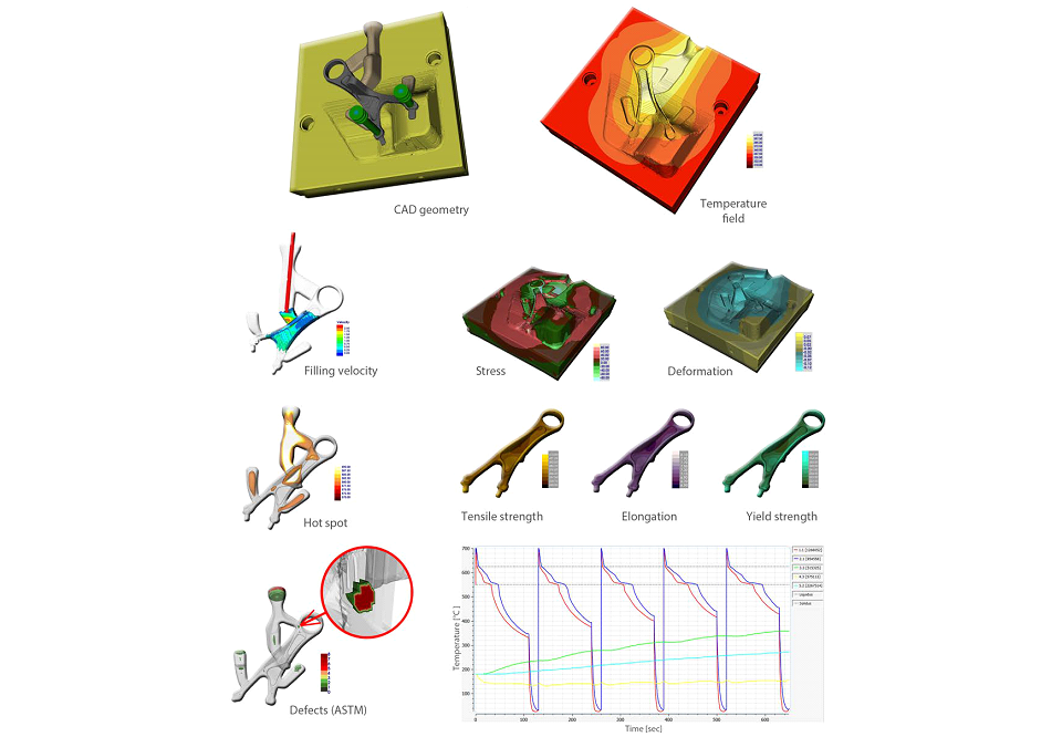
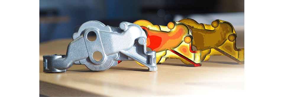
Permanent Die Casting
- CAD Geometry
- Temperature Field
- Filling Velocity
- Stress
- Deformation
- Hot Spot
- Tensile Strength
- Elongation
- Yield Strength
- Defects (ASTM)
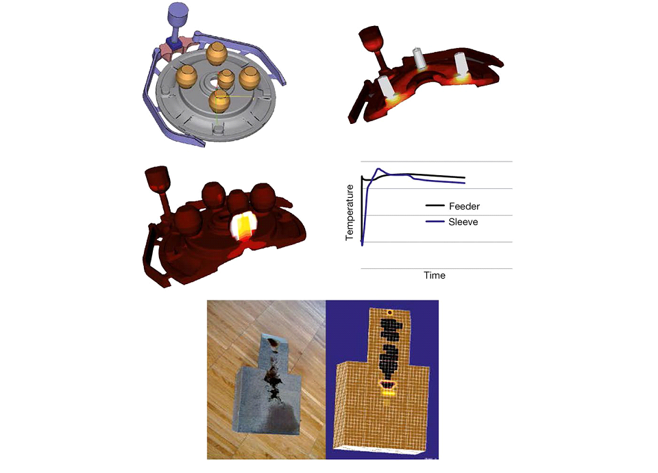
Sand Casting
- The total riser and gating system, filter and core are the part of the model
- Precise physical data for exothermic materials are available
- Graphite expansion and precise defect prediction are typical requirements
- Validation with experiments is fundamental for good simulation results
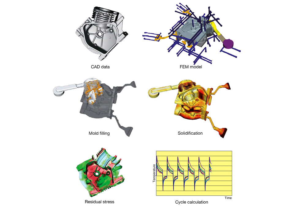
High Pressure Die Casting
- CAD Data
- FEM Model
- Mold Filling
- Solidification
- Residual Stress
- Cycle Calculation
The simulation of solidification is the base for the prediction of porosities, residual stress and deformation. Several cycles are calculated to draw near the steady state.
Low Pressure Die Casting
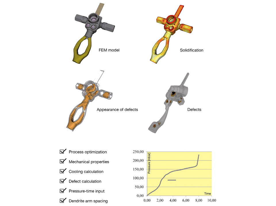
- Process Optimization
- Mechanical Properties
- Cooling Calculation
- Defect Calculation
- Pressure-time Input
- Dendrite Arm Spacing
Investment Casting
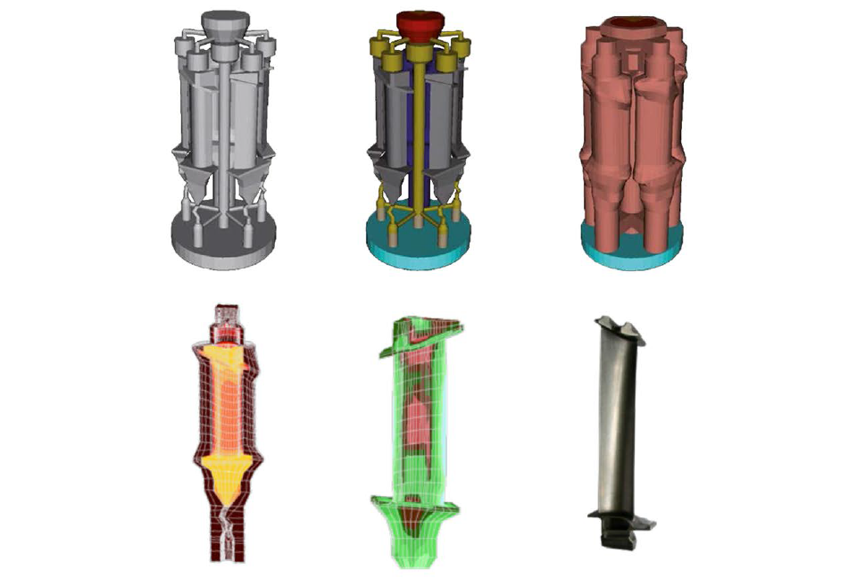
Precise geometry with high level of detail is the reason for real success.
Optimized riser and gating system leads to a minimal deformed part. Simulation of temperature, solidification, stress and deformation are the keys to reach optimum.
Continuous Casting
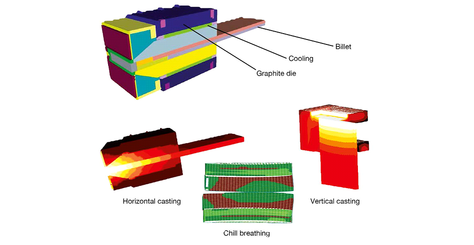
The thermal and mechanical equations are coupled. Thus the material flow and the shrinkage of the billet can be determined as well as the gap formation and gap dependent heat transfer.
- Primary and secondary cooling
- Material and heat transport
- Pull (and push) conditions
- Contact between strand and graphite chill
- Contact between graphite and copper chill
- Heat transport within cooling lines
Heat Treatment
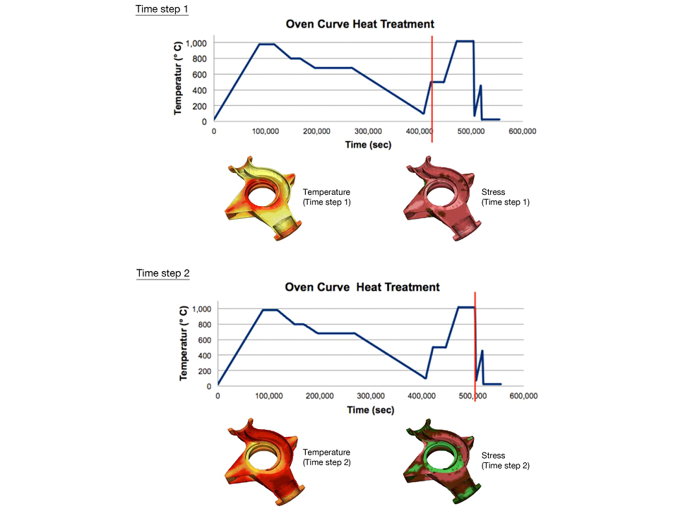
The changing residual stresses while heat treatment can be calculated in order to optimize the oven curve to reduce deformation.
Stress/Distortion/Lifetime
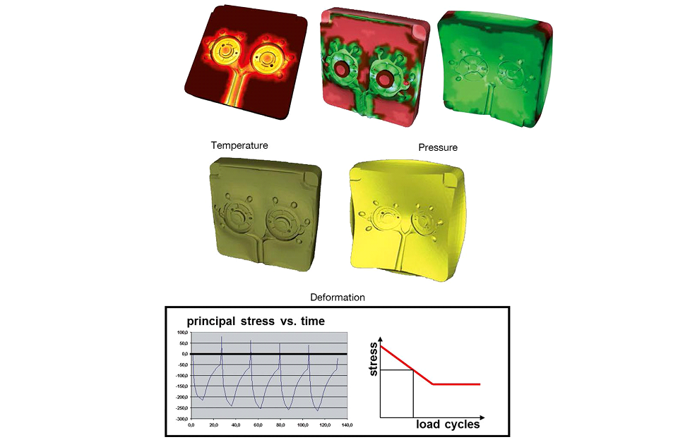
High differences in temperature during a high pressure die casting cycle and enormous pressure peaks are the reasons for local cracking in the die and reduce the lifetime significantly.
Evaluation of Mechanical Properties
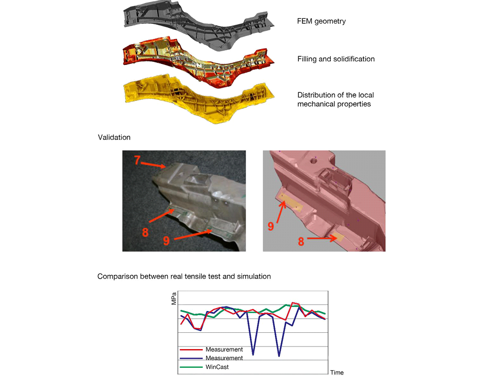
Complex thin-walled aluminum casting.
Stress and Crack Investigation
Fast. Precise. Easy to Handle.
 Dr. Dillingham served in the U.S. Army during the Persian Gulf War and served as an investigator for the National Institute for Health (NIH) studying the needs of patients with limb loss. He was amazed by the time and effort required to make a hard socket fit a changing limb. He was inspired to expand the options available to lower limb amputees.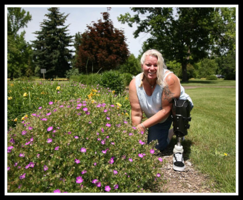
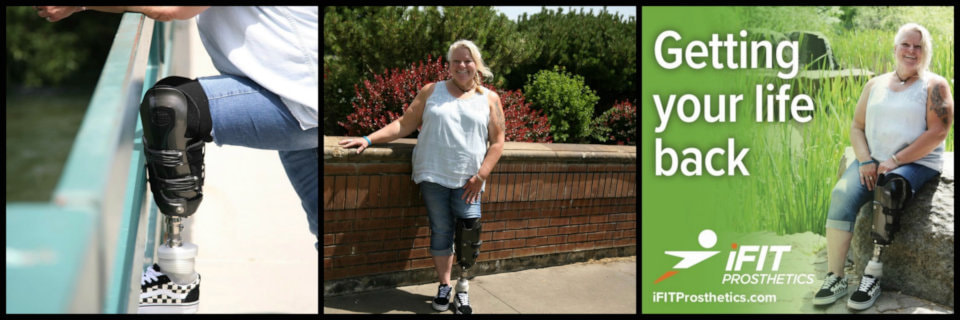
 Diana recently discovered iFit Prosthetics. She faced tremendous challenges finding the right fit for her prosthetic need. According to Diana, “The iFit Prosthetics socket system has given me hope. I have a VERY challenging limb and the adjustable iFit Prosthetic was the one that worked for me when the others have only brought me disappointment. I was on the brink of surgery to have an above knee amputation due to the tremendous pain of other sockets. With my iFit Prosthetic I have resumed my normal life without surgery. Thank you for changing my life and eliminating the pain.” Diana’s is one of many success stories the team at iFit Prosthetics hears from patients.
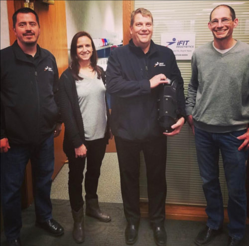
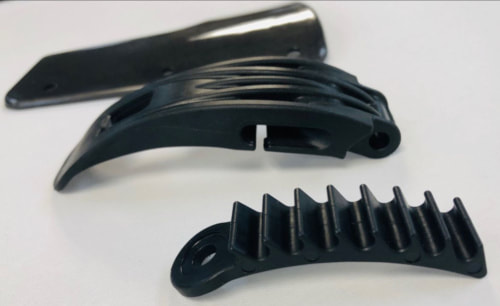
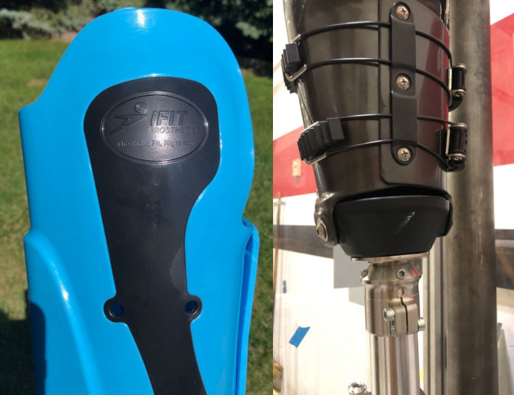 Advanced Design Concepts is proud to have supported the iFit Prosthetic product development cycle since its infancy. Our engineers collaborated with Dr. Dillingham to design, refine, develop prototypes and prosthetic limb, resulting in the current lower limb prosthetic on the market today. Not only have we helped in the development stage, we are also manufacturing elements of the device. All of the strong plastic component parts are injection molded at ADC and assembled at our facility in Pewaukee, Wisconsin. iFit Prosthetics intentionally sources any component not manufactured at ADC using U.S.-based vendor companies.

 SportingSmiles is changing the world one smile at a time. ADC’s
  In middle school, McCarthy was accidentally hit with a wayward baseball bat during gym class. The result: he lost four front teeth, but the accident led to today’s successful business. After the accident, McCarthy took care to wear mouth guards when playing sports but he found that over-the-counter guards were “uncomfortable and boring.” McCarthy asked his father, a dentist, to teach him how to make custom guards and began producing some with different colors, patterns, and graphics, drawing interest from family and friends. Sporting Smiles is in the smile retention business with a wide array of injury prevention and smile enhancement products and celebrating 10 years in business. Fun to see them in the news this recently!