Much like a camera takes photos of the real world in two dimensions, structured light scanners capture images of the real world in three dimensions.
A fringe pattern, or series of lines, is projected onto an object. The lines curve and distort as they lay on the contours and surfaces of the part. Two cameras work in tandem to capture this image and 3D scanning software processes the image using complex computations to create a digitized 3D snapshot.
Just like a regular camera, the scanner can only take one still image at a time. Target points placed on and around the object allow the software to triangulate its orientation and location within a three dimensional coordinate system. Many individual images must be taken to fully encompass the part.
The images are then assembled into a “point cloud” or millions of individual points in space. Finally, the points are connected and tessellated into a polygonal representation of the real-life object with an accuracy of up to .001”.
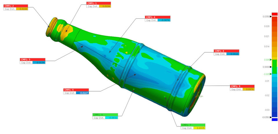
After a part is 3D scanned and converted into an .STL file it is imported into inspection software along with the corresponding CAD file. Whether the part was scanned in a “free” (natural) or “fixed” (constrained) state the scan will first be aligned to the CAD file via the designated alignment requirements.
Based on part drawings and/or customer requests, parts can be aligned in many different ways: feature based datum alignments, best fit, datum and best fit combinations, RPS, 3-2-1, or transform alignments. Once aligned, an overall surface profile inspection is performed.
A uniform boundary is defined around the part’s entire surface both above and below the CAD or “nominal” surface. The resulting image is a color-plot of the part with green denoting areas that are within tolerance, warm colors (yellow, orange and red) depicting areas that are above the defined tolerance zone and cold colors (blues) showing areas that are under tolerance.
For many parts an overall surface profile inspection is adequate because, it simultaneously measures form, size, orientation and sometimes location within a specified tolerance. For more in-depth inspections local profile zones, 2D profiles and thickness inspections can be performed.
Many GD&T call-outs are measurable such as, flatness, cylindricity, parallelism, perpendicularity, position, concentricity, run-out and dimensions. Once completed, the results are then compiled into a report. For multiple part inspections the process is then repeated and copies of all reports and scan files are sent to customer.
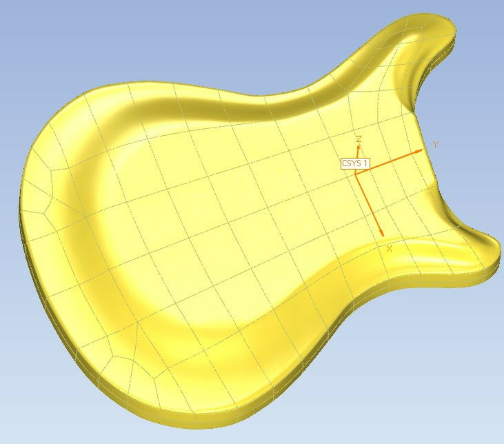
Once the need for a CAD model is determined the reverse engineering process can begin. First, an .STL file is generated by scanning the physical part. A Non-Uniform Rational Basis Spline (NURBS) surface is suitable when a static `true to life’ model is desired.
The .STL file is, in essence, “digitally shrink wrapped” to create a model of the desired geometry along with organic qualities such as warp and imperfections. Many imperfections and defects can be minimized with a NURBS surface making them versatile models ideal for sand cores.
When a more prismatic “perfect” model is needed the part scan can be imported into a CAD package. A new model is created by overlaying the part’s actual geometry.
Manufacturing intent can be applied to the model for tooling and machining purposes. It is possible for the model to be fully parametric when future design changes are anticipated.
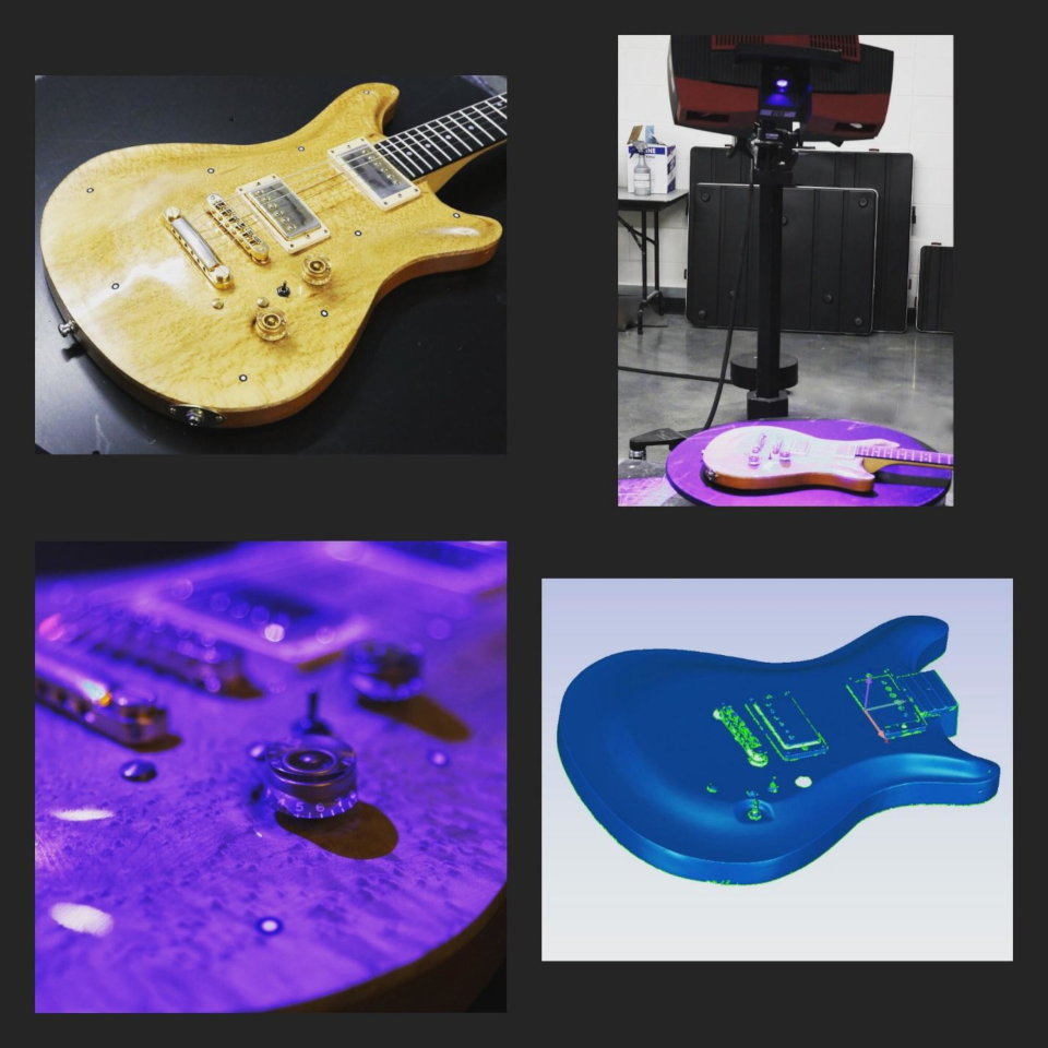
A 3D digitized representation of an object provides the foundation for a multitude of services such as Reverse Engineering and Quality Control.
Reverse engineering: create machinable models for replacing old tooling, sand cores, recreating discontinued products, preserving art/history, 3D printing, creating CAD models of parts that never had one, scaling or altering existing items and more.
Quality Control: GD&T inspections, multiple part comparisons, PPAP inspections and more.
Upon receipt of the part, Scanning and Inspection work can typically take 2-3 business days depending on quantity, part complexity and scope of work. Larger quantities of 5 or more, larger parts such as airplanes and more complex inspections (full dimensional layouts) may add additional work time.
Reverse engineering usually takes around 3-6 business days and will be dependent on the scope of work, NURBS surfacing vs. fully parametric modeling.
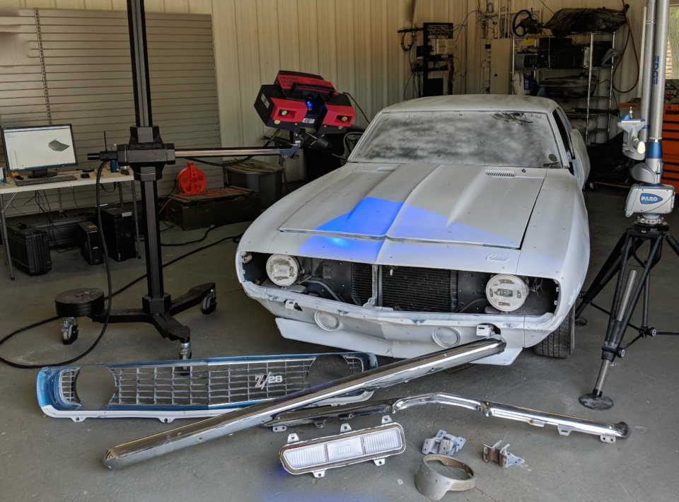
Shipping: Typically parts that fit on a standard size pallet can be received 3D scanned in-house using both high resolution structured blue light scanners and blue laser light coordinate measuring machine (CMM) arm scanners. Other large components that are deliverable can be scanned such as cars, trucks and other large objects.
On-Site: For objects too large, delicate, important to production, secret or time sensitive the 3D scanning equipment can travel to the location of the part. Cars, airplanes, construction equipment, works of art, large castings and production tooling can be scanned on-site without moving, uninstalling or disturbing the part.
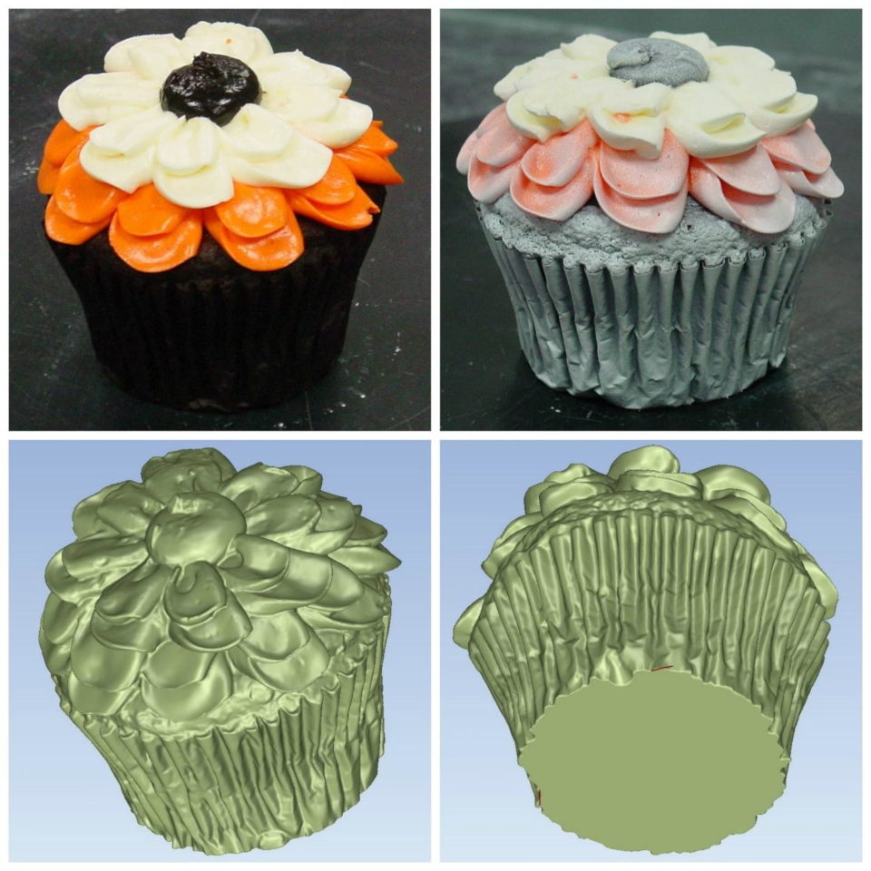
Whether it is 3D scanning for the sake of art preservation, quality control or reverse engineering, having a customized engineering plan for part inspection or reverse engineering will help ensure you meet your budgetary requirements.
From surface profile color-plots, geometric dimensioning and tolerancing (GD&T) dimensional layouts and Production Part Approval Process (PPAP) inspections there is a wide range of quality control services available. NURBS surfacing provides a quick and `true to life’ reverse engineering model. Accurate prismatic model services are available as non-parametric and fully-parametric.
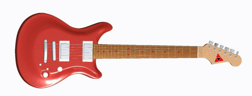
When a part is scanned it is measured as a point cloud. The point cloud is then polygonized into a geometric mesh known as an .STL (stereolithography) file. Parametric models can be constructed in both PTC Creo (Pro/e) and Solidworks.
Universal, non-parametric models can be provided in many formats including: .STP and .IGES.
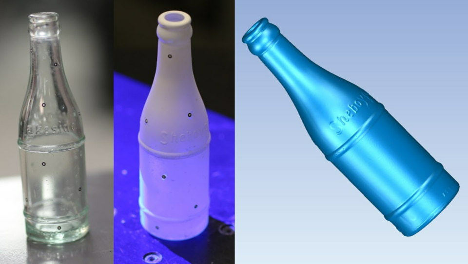
ADC utilizes non-destructive laser and structured blue light scanning technology. Heavy dirt and oil will be removed with non-harmful cleaning products prior to the 3D scanning process ensuring delicate surface finishes are left intact.
Blue light technology can capture a variety of surface finishes without any special treatment, including many cast surfaces, light colored plastics and other light matte finishes. Shiny and dark surfaces, by nature, reflect too much or not enough light making it difficult to fully capture.
In many cases the object must be coated with developer spray (talcum powder) or even white spray paint when possible. The use of adhesive target points may be necessary as well. External surface capturing is adequate for most applications.
More complicated parts, such as investment castings, may need to be sectioned by destructive means to expose internal geometry for 3D capturing. The whole exterior is scanned first, then the individual pieces after sectioning. All scan files are assembled into a single representation of the object inside and out making for a more complete inspection or reverse engineering project.
Onsite scanning requires hard and level ground to support the scanning machines and enough space to move the equipment around. Once the item is scanned, target points are easily removed and the developer spray is washed off leaving your part in the same state as before the process began.